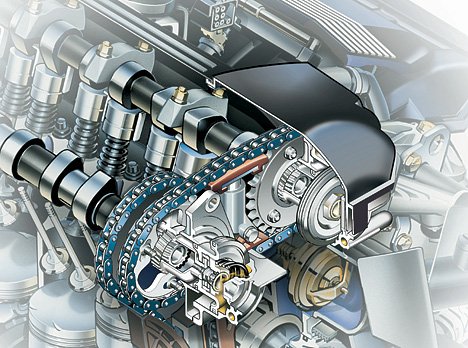
The Valvetronic system is the first variable valve timing system to offer continuously variable timing (on both intake and exhaust camshafts) along with continuously variable intake valve lift, from ~0 to 10 mm, on the intake camshaft only. Valvetronic-equipped engines are unique in that they rely on the amount of valve lift to throttle the engine rather than a butterfly valve in the intake tract. In other words, in normal driving, the 'gas pedal' controls the Valvetronic hardware rather than the throttle plate First introduced by BMW on the 316ti compact in 2001, Valvetronic has since been added to many of BMW's engines. The Valvetronic system is coupled with BMW's proven double-VANOS, to further enhance both power and efficiency across the engine speed range. Valvetronic will not be coupled to BMW's N53 and N54, 'High Precision Injection' (gasoline direct injection) technology due to lack of room in the cylinder head. Cylinder heads with Valvetronic use an extra set of rocker arms, called intermediate arms (lift scaler), positioned between the valve stem and the camshaft. These intermediate arms are able to pivot on a central point, by means of an extra, electronicly actuated camshaft. This movement alone, without any movement of the intake camshaft, can open or close the intake valves. Because the intake valves now have the ability to move from fully closed to fully open positions, and everywhere in between, the primary means of engine load control is transferred from the throttle plate to the intake valvetrain. By eliminating the throttle plate's 'bottleneck' in the intake track, pumping losses are reduced, fuel economy and responsiveness are improved.
Saturday, March 14, 2009
Valvetronic
VANOS (Variable Nockenwellen Steuerung)
Ball Valve
A ball valve (like the butterfly valve, one of a family of valves called quarter turn valves) is a valve that opens by turning a handle attached to a ball inside the valve. The ball has a hole, or port, through the middle so that when the port is in line with both ends of the valve, flow will occur. When the valve is closed, the hole is perpendicular to the ends of the valve, and flow is blocked. The handle position lets you 'see' the valve's position.
Ball valves are durable and usually work to achieve perfect shutoff even after years of disuse. They are therefore an excellent choice for shutoff applications (and are often preferred to globe valves and gate valves for this purpose). They do not offer the fine control that may be necessary in throttling applications but are sometimes used for this purpose.
The body of ball valves may be made of metal, ceramic, or plastic. The ball may be chrome plated to make it more durable.
There are three general types of ball valves: full port, standard port, and reduced port.

- A full port ball valve has an oversized ball so that the hole in the ball is the same size as the pipeline resulting in lower friction loss. Flow is unrestricted, but the valve is larger.
- A standard port ball valve is usually less expensive, but has a smaller ball and a correspondingly smaller port. Flow through this valve is one pipe size smaller than the valve's pipe size resulting in slightly restricted flow.
- In reduced port ball valves, flow through the valve is two pipe sizes smaller than the valve's pipe size resulting in restricted flow.

Gate Valve
A gate valve is a valve that opens by lifting a round or rectangular gate out of the path of the fluid. The distinct feature of a gate valve is the sealing surfaces between the gate and seats are planar. The gate faces can form a wedge shape or they can be parallel. Gate valves are sometimes used for regulating flow, but many are not suited for that purpose, having been designed to be fully opened or closed. When fully open, the typical gate valve has no obstruction in the flow path, resulting in very low friction loss. Bonnets provide leakproof closure for the valve body. Gate valves may have a screw-in, union, or bolted bonnet. Screw-in bonnet is the simplest, offering a durable, pressure-tight seal. Union bonnet is suitable for applications requiring frequent inspection and cleaning. It also gives the body added strength. Bolted bonnet is used for larger valves and higher pressure applications. Another type of bonnet construction in a gate valve is pressure seal bonnet. This construction is adopted for valves for high pressure service, typically in excess of 2250 psi. The unique feature about the pressure seal bonnet is that the body - bonnet joints seals improves as the internal pressure in the valve increases, compared to other constructions where the increase in internal pressure tends to create leaks in the body-bonnet joint.
Gate valves are characterised as having either a rising or a nonrising stem. Rising stems provide a visual indication of valve position. Nonrising stems are used where vertical space is limited or underground.
Globe valves
Globe valves are named for their spherical body shape. The two halves of the valve body are separated by a baffle with a disc in the center. Globe valves operate by screw action of the handwheel. They are used for applications requiring throttling and frequent operation. Since the baffle restricts flow, they're not recommended where full, unobstructed flow is required. A bonnet provides leakproof closure for the valve body. Globe valves may have a screw-in, union, or bolted bonnet. Screw-in bonnet is the simplest bonnet, offering a durable, pressure-tight seal. Union bonnet is suitable for applications requiring frequent inspection or cleaning. It also gives the body added strength. Bolted bonnet is used for larger or higher pressure applications. Many globe valves have a class rating that corresponds to the pressure specifications of ANSI 16.34. Other different types of valve usually are called globe style valves because of the shape of the body or the way of closure of the disk. As an example typical swing check valves could be called globe type.
VVT-i
VVT-i, or Variable Valve Timing with intelligence, is an automobile variable valve timing technology developed by Toyota. The Toyota VVT-i system replaces the Toyota VVT offered starting in 1991 on the 4A-GE 20-Valve engine. The VVT system is a 2-stage hydraulically controlled cam phasing system. VVT-i, introduced in 1996, varies the timing of the intake valves by adjusting the relationship between the camshaft drive (belt, scissor-gear or chain) and intake camshaft. Engine oil pressure is applied to an actuator to adjust the camshaft position. In 1998, 'Dual' VVT-i (adjusts both intake and exhaust camshafts) was first introduced in the RS200 Altezza's 3S-GE engine. Dual VVT-i is also found in Toyota's new generation V6 engine, the 3.5L 2GR-FE V6. This engine can be found in the Avalon, RAV4, and Camry in the US, the Aurion in Australia, and various models in Japan, including the Estima. Other Dual VVT-i engines will be seen in upcoming Toyota models, including a new 4 cylinder Dual VVT-i engine for the new generation 2007/2008 Corolla. Another notable implementation of the Dual VVT-i is the 2GR-FSE D-4S engine of the Lexus GS450h. By adjusting the valve timing, engine start and stop occur virtually unnoticable at minimum compression, and fast heating of the catalytic converter to its light-off temperature is possible, thereby reducing HC emissions considerably.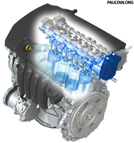
VTEC
VTEC was initially designed to increase the power output of an engine to 100 ps/liter or more while maintaining practicality for use in mass production vehicles. Some later variations of the system were designed solely to provide improvements in fuel efficiency, or increased power output as well as improved fuel efficiency.
Catalytic Converter
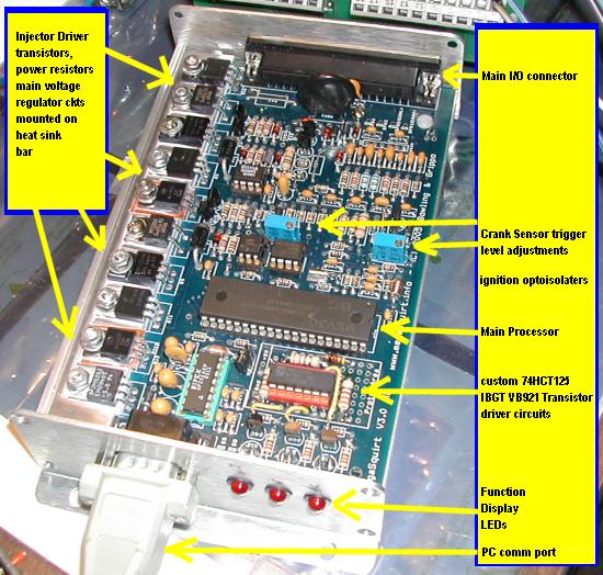
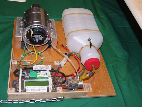
MegaSquirt
MegaSquirt is an aftermarket electronic fuel injection (EFI) controller designed to be used with a wide range of internal combustion engines. It is an open project headed by Bruce Bowling and Al Grippo, engineers that work on the U.S. East Coast. The project's do-it-yourself approach makes it the least-expensive system for this purpose. Basic costs are below US$200 as of 2005, although this can vary widely depending on application. MegaSquirt is a successor of sorts to Bowling and Grippo's earlier EFI332 design, which was more complex yet more powerful system (at least initially). The EFI332 project started around 1995, and culminated in the release of about 200 kits in 2000. The system used a 32-bit MC68332 microcontroller from Motorola, hence the name. A steep learning curve is believed to have prevented the system from gaining wider acceptance. The two engineers decided to simplify the design and focus on managing the fuel injectors (the EFI332 could also control the spark plug ignition system if so desired). The version 1.0 MegaSquirt used an 8-bit Motorola MC68HC908 microcontroller, but a later MegaSquirt-II upgrade included a 16-bit MC9S12. It is likely that a future version will use a 32-bit processor. The assembled controller takes input from a few different sensors in order to manage the fuel injectors, including a throttle position sensor (TPS), exhaust gas oxygen sensor (EGO or O2 sensor), MAP sensor, intake air temperature sensor (IAT), and a coolant temperature sensor (CLT). The latter two sensors themselves are usually the General Motors type, although you can recalibrate the controller to use other sensors. There are several related projects, including:
Butterfly Valve
A Butterfly valve is a type of flow control device, used to make a fluid start or stop flowing through a section of pipe. The valve is similar in operation to a ball valve. A flat circular plate is positioned in the center of the pipe. The plate has a rod through it connected to a handle on the outside of the valve. Rotating the handle turns the plate either parallel or perpendicular to the flow of water, shutting off the flow. It is a very robust and reliable design. However, unlike the ball valve, the plate does not rotate out of the flow of water, so that a pressure drop is induced in the flow. There are three types of butterfly valve: Butterfly valves are also commonly utilised in conjunction with carburetors to control the flow of air through the intake manifold and hence the flow of fuel and air into an internal combustion engine. The butterfly valve in this circumstance called a throttle as it is 'throttling' the engines aspiration. It is controlled via a cable or electronics by the furthest right pedal in the drivers footwell (although adaptions for hand control do exist). This is why the accelerator pedal in some countries is called a throttle pedal.

Butterfly Valve
Weber carburetors
Weber carburetors were originally produced in Italy by Edoardo Weber as part of a conversion kit for 1920s Fiats. Weber pioneered the use of twin barrel carburetors with two barrels (or venturi) of different sizes, the smaller one for low speed running and the larger one optimised for high speed use. In the 1930s Weber began producing twin barrel carburetors for motor racing where two barrels of the same size were used. These were arranged so that each cylinder of the engine has its own carburetor barrel. These carburetors found use in Maserati and Alfa Romeo racing cars. In time, Weber carburetors were fitted to standard production cars and factory racing applications on automotive marques such as Abarth, Alfa Romeo, Aston Martin, BMW, Ferrari, Fiat, Ford, Lamborghini, Lancia, Lotus, Maserati, Porsche, Triumph, and Volkswagen. In the United States Weber Carburetors are sold for both street and off road use. They are sold in what is referred to as a Weber Conversion kit. A Weber conversion kit is a complete package of Weber Carburetor, intake manifold or manifold adapter, throttle linkage, air filter and all of the necessary hardware needed to install the Weber on a vehicle.
Diesel Particulate Filter
A Diesel Particulate Filter, sometimes called a DPF, is device designed to remove Diesel Particulate Matter or soot from the exhaust gas of a Diesel engine, most of which are rated at 85% efficiency, but often attaining efficiencies of over 90%. A Diesel-powered vehicle with a filter installed will emit no visible smoke from its exhaust pipe.

In addition to collecting the particulate, a method must be designed to get rid of it. Some filters are single use (disposable), while others are designed to burn off the accumulated particulate, either through the use of a catalyst (passive), or through an active technology, such as a fuel burner which heats the filter to soot combustion temperatures, or through engine modifications (the engine is set to run a certain specific way when the filter load reachs a pre-determined level, either to heat the exhaust gasses, or to produce high amounts of No2, which will oxidize the particualte at relatively low temperatures). This procedure is known as 'filter regeneration.' Fuel sulfur interferes many 'Regeneration' strategies, and all jurisdictions that are interested in reduction of particulate emissions, are also passing regulations governing fuel sulfur levels.
Selective Catalytic Reduction (SCR)
Selective Catalytic Reduction (SCR), a process where a gaseous or liquid reductant (most commonly ammonia or urea) is added to the flue gas stream and is absorbed onto a catalyst. The reductant reacts with NOx in the flue gas to form H2O and N2.
Specialty Catalytic Converters are required to make an SCR system work, the current options being a Vanadium based catalyst, or a catalyst with Zeolites in the washcoat. In some jurisdictions use of a Vanadium based catalyst are frowned on (California) and the Zeolite type preferred, however Vanadium offers better performance.

SCR catalysts function well only within a narrow temperature window, and for OEM installations the Engine Control Unit is specially programmed to keep the exhaust gas temperature in that range

MAP sensor
An engine control system that uses manifold absolute pressure to calculate air mass, is using the speed-densityEngine speed (RPM) and air temperature are also necessary to complete the speed-density calculation. Not all fuel injected engines use a MAP sensor to infer mass air flow, some use a MAF sensor (mass air flow).

EURO V
EURO V is the most recent set in a series of mandatory European emission standards applying to new road vehicles sold in the EU. For heavy duty vehicles (lorries) the standards apply to vehicles brought on the market from October 2008. It requires Heavy Goods Vehicles (HGVs) to emit no more than 2.0 g/kWh of NOx and 0.02 g/kWh of PM. As yet, there is no Euro V standard applying for passenger cars, but a recent proposal suggests to limit diesel car emissions to 0.200 g/km of NOx and 0.005 g/km of Particulate Matter (PM), petrol cars to 0.060 g/km NOx and 0.005 g/km PM. The standards do not mandate the application of specific technologies, but it is widely expected that diesel particulate filters will need to be fitted in diesel vehicles to comply with the PM standard.
Mass Airflow Sensor
A mass airflow sensor is used to determine the mass of air entering the engine. The air mass information is necessary to calculate and deliver the correct fuel mass to the engine. Air is a gas, and its density changes as it expands and contracts with temperature and pressure. In automotive applications, air density varies with the vehicle's operating environment, and is an ideal application for a mass sensor. (See stoichiometric, ideal gas law, and density.) There are two common types of mass airflow sensors in usage on gasoline engines. They are the vane meter and the hot wire. Neither design employs technology that measures air mass directly. However, with an additional sensor or two, the engine's air mass flow rate can be accurately determined. Both approaches are used almost exclusively on gasoline burning, EFI (electronic fuel injection) engines. Both sensor designs output a 0 - 5.0 volt signal that is proportional to the air mass flow rate, and both sensors have an IAT sensor (intake air temperature) incorporated into their housings. When a MAF is used in conjunction with an exhaust gas oxygen sensor, the engine's air/fuel ratio can be controlled very accurately. The MAF sensor provides the open-loop predicted air flow information (the measured air flow) to the engine's ECU, and the EGO sensor provides closed-loop feedback in order to make minor corrections to the predicted air mass.
Babbitt metal
Babbitt metal, also called white metal, is an alloy used to provide the bearing surface in a plain bearing. It was invented in 1839 by Isaac Babbitt in Taunton, Massachusetts, USA. The term is used today to describe a series of alloys used as a bearing metal. Babbit metal is characterized by its resistance to gall. Common compositions for Babbitt alloys: Originally used as a cast in place bulk bearing material, it is now more commonly used as a thin surface layer in a complex, multi metal structure. Babbitt metal is soft and easily damaged, and seems at first sight an unlikely candidate for a bearing surface, but this appearance is deceptive. The structure of the alloy is made up of small hard crystals dispersed in a matrix of softer alloy. As the bearing wears the harder crystal is exposed, with the matrix eroding somewhat to provide a path for the lubricant between the high spots that provide the actual bearing surface.
Babbit Bearing Metals |

BlueTec
This system makes these vehicles 45-state and 50-state legal respectively in the United States, and is expected to meet all emissions regulations through 2009. It also makes DaimlerChrysler the only car manufacturer in the the US committed to selling diesel models in the 2007 model year. and uses an oxidising catalytic converter and particular filter combined with other NO

CVCC
Honda CVCC engines have normal inlet and exhaust valves, plus a small auxiliary inlet valve which provides a relatively rich air / fuel mixture to a volume near the spark plug. The remaining air / fuel charge, drawn into the cylinder through the main inlet valve is leaner than normal. The volume near the spark plug is contained by a small perforated metal plate. Upon ignition flame fronts emerge from the perforations and ignite the remainder of the air / fuel charge. The remaining engine cycle is as per a standard four stroke engine.
This combination of a rich mixture near the spark plug, and a lean mixture in the cylinder allowed stable running, yet complete combustion of fuel, thus reducing CO (carbon monoxide) and hydrocarbon emissions.

Stratified charge engine
The stratified charge engine is a type of internal-combustion engine, similar in some ways to the Diesel cycle, but running on normal gasoline. The name refers to the layering of fuel/air mixture, the charge inside the cylinder. In a traditional Otto cycle engine the fuel and air are mixed outside the cylinder and are drawn into it during the intake stroke. The air/fuel ratio is kept very close to stoichiometric, which is defined as the exact amount of air necessary for a complete combustion of the fuel. This mixture is easily ignited and burns smoothly. The problem with this design is that after the combustion process is complete, the resulting exhaust stream contains a considerable amount of free single atoms of oxygen and nitrogen, the result of the heat of combustion splitting the O2 and N2 molecules in the air. These will readily react with each other to create NOx, a pollutant. A catalytic converter in the exhaust system re-combines the NOx back into O2 and N2 in modern vehicles. A Diesel engine, on the other hand, injects the fuel into the cylinder directly. This has the advantage of avoiding premature spontaneous combustion—a problem known as detonation or ping that plagues Otto cycle engines—and allows the Diesel to run at much higher compression ratios. This leads to a more fuel-efficient engine. That is why they are commonly found in applications where they are being run for long periods of time, such as in trucks.

E85
E85 is an alcohol fuel mixture of 85% ethanol and 15% gasoline, by volume. ethanol derived from crops (bioethanol) is a biofuel. E85 as a fuel is widely used in Sweden and is becoming increasingly common in the United States, mainly in the Midwest where corn is a major crop and is the primary source material for ethanol fuel production. E85 is usually used in engines modified to accept higher concentrations of ethanol. Such flexible-fuel engines are designed to run on any mixture of gasoline or ethanol with up to 85% ethanol by volume. The primary differences from non-FFVs is the elimination of bare magnesium, aluminum, and rubber parts in the fuel system, the use of fuel pumps capable of operating with electrically-conductive (ethanol) instead of non-conducting dielectric (gasoline) fuel, specially-coated wear-resistant engine parts, fuel injection control systems having a wider range of pulse widths (for injecting approximately 30% more fuel), the selection of stainless steel fuel lines (sometimes lined with plastic), the selection of stainless steel fuel tanks in place of terne fuel tanks, and, in some cases, the use of acid-neutralizing motor oil. For vehicles with fuel-tank mounted fuel pumps, additional differences to prevent arcing, as well as flame arrestors positioned in the tank's fill pipe, are also sometimes used.
FADEC - Full Authority Digital Engine Control.
FADEC is the acronym for Full Authority Digital Engine Control. It is a system consisting of a digital computer (called EEC /Electronic Engine Control/ or ECU /Electronic Control Unit/) and its related accessories which control all aspects of aircraft engine performance. FADECs have been produced for both piston engines and jet engines, their primary difference due to the different ways of controlling the engines. Electronics' superior accuracy led to early generation analogue electronic control first used in Concorde's Rolls-Royce Olympus 593 in the 1960s. Later in the 1970s NASA and Pratt and Whitney experimented with the first experimental FADEC, first flown on an F-111 fitted with a highly modified Pratt & Whitney TF-30 left engine. The experiments led to Pratt & Whitney F100 and Pratt & Whitney PW2000 being the first military and civil engines respectively fitted with FADEC and later the Pratt & Whitney PW4000 as the first commercial 'Dual FADEC' engine. The aircraft's thrust lever sends electrical signals (pilot's command, may also be the autothrottle) to the FADEC. The FADEC digitally calculates and precisely controls the fuel flow rate to the engines giving precise thrust. In addition to the fuel metering function, the FADEC performs numerous other control and monitoring functions such as Variable Stator Vanes (VSV's) and Variable Bleed Valves (VBV's) control, cabin bleeds and power off-takes control, control of starting and re-starting, turbine blade and vane cooling and blade tip clearance control, thrust reversers control, engine health monitoring, oil debris monitoring and vibration monitoring. The inputs come from various aircraft and engine sensors. Apart from the key parameters that are monitored for a safe thrust control (shaft rotational speeds, pressures and temperatures at various points along the gas path) the FADEC also monitors hundreds of various analog, digital and discrete data coming from the engine subsystems and related aircraft systems, providing a fully redundant and fault tolerant engine control.
For radio controlled jet engine
Hybrid Synergy Drive (HSD)
Hybrid Synergy Drive (HSD) is a set of hybrid car technologies developed by Toyota and used in that company's Prius, Highlander Hybrid, Camry Hybrid, Lexus RX 400h, and Lexus GS 450h automobiles. It combines the characteristics of an electric drive and a continuously variable transmission, using electricity and transistors in place of toothed gears. The Synergy Drive is a drive-by-wire system with no direct mechanical connection between the engine and the engine controls: both the gas pedal and the gearshift lever in an HSD car merely send electrical signals to a control computer.
HSD is a refinement of the original Toyota Hybrid System (THS) used in the 1997–2003 Toyota Prius. As such it is occasionally referred to as THS II. The name was changed in anticipation of its use in vehicles outside the Toyota brand (Lexus).
when required to classify the transmission type of an HSD vehicle (such as in standard specification lists or for regulatory purposes), Toyota describes HSD-equipped vehicles as having E-CVT (Electronically-controlled Continuously Variable Transmission).

Toyota Hybrid Synergy Drive
Regenerative Brake
A regenerative brake is an apparatus, a device or system which allows a vehicle to recapture part of the kinetic energy that would otherwise be lost to heat when braking and make use of that power either by storing it for future use or feeding it back into a power system for other vehicles to use.
It is similar to an electromagnetic brake, which generates heat instead of electricity and is unable to completely stop a rotor.
Regenerative brakes are a form of dynamo generator, originally discovered in 1832 by Hippolyte Pixii. The dynamo's rotor slows as the kinetic energy is converted to electrical energy through electromagnetic induction. The dynamo can be used as either generator or brake by converting motion into electricity or be reversed to convert electricity into motion.

It is estimated that regenerative braking systems in vehicles currently reach 31.3% electric generation efficiency, with most of the remaining energy being released as heat; the actual efficiency depends on numerous factors, such as the state of charge of the battery, how many wheels are equipped to use the regenerative braking system, and whether the topology used is parallel or serial in nature. The system is no more efficient than conventional friction brakes, but reduces the use of contact elements like brake pads, which eventually wear out. Traditional friction-based brakes must also be provided to be used when rapid, powerful braking is required.